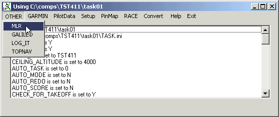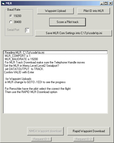
To work witn an MLR 24SP XC or a Renschler SOL 17 choose the Menu Option OTHER/ MLR
The MLR has to be in Level 2 or 3.
The Serial Port in the MLR, Telephone handle, has to be active.

Decide on the baudrate to be used , the default is 19200, the slowest.
And then press on the Score a Pilot track button , which uses the Rapid PMLR Download to get a track log

Save MLR Settings allows one to store the used comport and baudrate
for a MLR in the TP.ini file under the MLR section.
Values are MLR_COMPORT and MLR_BAUDRATE
Waypoint Upload will use the comp_id.csv file and send it to
the MLR.
Afterwards one can create an encrypted pilot number as a waypoint in
the MLR.
For a waypoint Upload the MLR must be in Level 2 or 3.
The serial port must be active.
18 December 2002 all MLR gave out wrong date stamps at the
same time period for a while. Garmin and Compeo were ok.
Snippet from a track log ...
-32.9048768430948,19.038302237168,409141318,0,734
-32.9048834647983,19.0382927656174,409141328,0,734
-32.9048024956137,19.0383380278945,647771367,0,219
-32.9031271208078,19.0386569593102,647771377,0,426
-32.9036877024919,19.0386094339192,409141369,1,426
-32.9047128092498,19.0384112857282,409141379,0,483
-32.9058489762247,19.0379683021456,409141389,0,667
Workaround, when a track is past the cut off time one can
manually with a YES/NO dialog carry on scoring the track.
For those 2 points this is fine, not a big problem. If there
are more, then the operator has to accept each faulty track point.
Maybe it helps setting the MLR Serial Port , Data Output, Format to TRACK for track output.
Use slowest baudrate initially.
Richard Hopkins [hoopy_hoppy@yahoo.co.uk]
This information copied from the manual page 10,
Version 2.0
Looking at the connector you will find 3 plastic location notches.
Using the same numbering scheme as the manual, pin 3 is directly between the
2 small notches. The other 4 pins are numbered clockwise.
Alternatively, if the GPS is held upright with the connector at the top, Pin
1 is at 6 o'clock 2 at 8, 3 at 10, 4 at 1 and 5 at 4.
Pin 1 is external antenna power supply output @ 2.7V. I wouldn't take more
than 50-100mA from here.
Pin 2 is DC input 10-20V
Pin 3 is NMEA / MLR data output
Pin 4 is NMEA / MLR data input
Pin 5 is Gnd (0V)
To wire your MLR to a PC DB9 serial port connect
MLR pin 3 to PC pin 2
MLR pin 4 to PC pin 3
MLR pin 5 to PC pin 5
The MLR connector is very similar to a mini-DIN socket, although the pin
layout is a bit different. Careful use of hot melt glue, might allow you to
reuse an old PC PS-2 mouse / keyboard connector.
Alternative method of making a plug
1) Put a thin layer of grease onto the MLR connector
2) Put a straight bit of wire (eg paperclips) with a wire soldered to it
into each pin hole.
3) Drip hotmelt glue over the connector. The grease should stop it sticking
to the MLR.
4) Ensure the glue fulls up the ring around the connector
5) When the glue has hardened, remove the "connector" you have just made
This should work with proper glue too.
The connector won't be very sturdy, but mine has lasted ages for downloading
flights to my PC. I wouldn't use it for connecting to a PDA in flight unless
you can make a good secure connector though.
Hope it works for you!
Although it worked for me, don't come crying if you blow up your MLR / PC or
glue yourself to the MLR!